|
SPECIAL
OFFERS
GIFT VOUCHERS |
TOUCH
TWIN KEY AND KEYER ASSEMBLY / OPERATION |
KIT
CONTENTS |
| R1 |
10K Brown - Black - Orange |
C1 |
100nf Marked 104 |
| R2 |
150R Brown - Green - Brown |
C2 |
47mf 16V Electrolytic |
| R3 |
Not used |
C3 |
..022 400V Yellow |
| R4 |
1K Brown - Black - Red |
C4 |
22pf |
| R5 |
750K Purple- Green - Yellow |
C5 |
470nf Marked .47k |
| R6 |
750K Purple- Green - Yellow |
C6 |
22pf Disc ceramic |
| VR1 |
100K |
|
1 Main PCB |
| VR2 |
22K |
|
2 Paddle PCB |
| VR3 |
1M |
|
1 IC Socket |
| VR4 |
1M |
|
1 Brass paddle mounting block |
| X1 |
4Mhz Resonator |
|
1 Alloy base |
| TR1 |
BC546 |
|
4 Rubber feet |
| TR2 |
7805 |
|
4 2.5mm Brass screws |
| IC1 |
PIC16C56 |
|
6 3mm Screws |
| 1 |
Relay |
|
2 Brass spacers |
| |
|
|
|
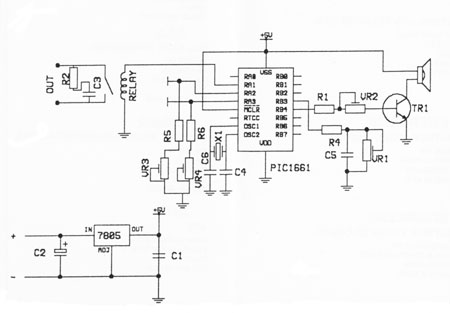
 Note : Fit capacitors C3, C4
and C6 to the outer holes or to the two holes
within the boxed area at each position.
Note : Fit capacitors C3, C4
and C6 to the outer holes or to the two holes
within the boxed area at each position. |
| |
ASSEMBLY
First identify all contponents
and their relevant position on the PCB then fit
R1 to R6, R3 is no longer used, solder each resistor
in place then trim off excess lead.
Fit Xl and Cl to C6 noting the polarity of C2,
solder in place and trim oft excess lead. Insert
TR1 and TR2 with the flat towards VR2 and fit
IC1 socket with the notch towards Xl. Solder in
place then trim off excess lead. Fit the DIL RELAY
along with VRI and VR2 and solder in.
Using the two 3mm screws fit the brass block to
the component side of the PCB then using the four
2.5mm screws fit the two paddles one each side
of the brass block with the track side of the
PCB pointing outwards. Make the connections between
the two paddles and the main PCB using two off
cuts of component lead. Insert each of the off
cuts into the holes marked dot and dash soldering
one end to the paddle then solder each of the
other ends to the main PCB ensuring they dont
touch the brass mounting screws.
Now check all work, reidentifv all components
and confirm their position on the PCB. Check all
solder joints and inspect for any solder bridges.
If all is satisfactory and BEFORE fitting IC1
apply between 8V and 16V DC to the + and - . Measure
the voltage between pins 5 and 14 on ICI socket,
it should be 5V, if not, investigate and DO NOT
insert IC1 until you have the correct voltage.
If all is well and with the power disconnected
insert ICl with the identification notch towards
Xl and connect a small speaker or earphones to
SP and apply power.
SETTING UP
Note: VR3 and VR4 control the dash and dot paddle
sensitivity which increase as the presets are
turned clockwise.
(1) Set VRl (speed) and VR3 to their mid positions.
(2) Set VR4 fully anti clock wise and VR2(volume)
fully clock wise.
(3) Touch and hold the dash paddle only between
the finger and thumb, dashes will be heard.
Now turn VR4 clockwise increasing the dot sensitivity
until alternating dots and dashes are heard then
turn back anti clock svisc until tlte dots stop.
Now touch and hold both the dot and dash paddles,
a smooth stream of alternating dots and dashes
should be heard. If they sound erratic then turn
VR3 a touch clock wise decreasing the dash sensitivity
and repeat step 4.
Note: The speed can not be altered when a character
is playing.
|
|
|
|
|
|
| |
|
|