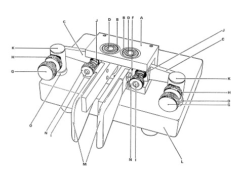
1. On the bearing block assembly
fit the two plastic paddles (M) using the
four 2.5mm screws. Note which way up the bearing
block mounts onto the steel base, using the
three mounting holes in the bearing block.
The plastic paddles can be fitted pointing
either up or as in the diagram, down.
2. Fit the two spring tension
studs (I) by inserting them into the holes
in the back of the bearing block so that the
threaded part passes through the contact arm
(C). Lightly secure using the two 3mm grub
screws in the two top holes in the bearing
block using the allen key supplied.
3. Fit the two springs (J) over
the adjusting studs, retaining them with the
spring adjuster nuts (N).
4. Slacken each of the 3mm grub
screws in turn and adjust the spring tension
studs back and forth until the two paddle
arms come out from the bearing block square
and are parallel to each other. When the correct
position has been reached tighten the two
grub screws.
5. On the base fit the four rubber
feet using the four short 3mm screws.
6. Using the three long 3mm screws,
washers and the 3mm solder tag fit the bearing
block to the base. The solder tag should be
fitted to the centre screw.
7. Loosely fit the two contact
adjusting pillars (K) with the four insulators
(0) using the two 4mm screws having first
placed washers and solder tags under the screw
heads.
8. Fit the two contact screws
(G) together with knurled locking nuts (H)
into the contact pillars (K). Adjust the contact
assemblies on each side to align the contacts
and finally tighten the two 4mm screws.
9. Using the cable clamp
and the short 4mm screw secure the cable to
the base. Connect each of the three cores
of the cable to each of the three solder tags.